Description
商品簡介

該板是基於德州儀器OPT3101 IC的距離感測器模組。
與使用反射光的強度來估計到物體的距離的傳統IR感測器不同,此板會發出以10 MHz脈衝的940 nm紅外光,然後測量反射信號的位置(延遲),該位置對應於與物體之間的距離和目標對象。 還有測量信號的幅度,該幅度指示對象的亮度/反射率/關閉程度。
該板具有三個通道,每個通道覆蓋大約50°至60°,從而為感測器提供了廣闊的視野(FOV)。 在有利的條件下,感測器可以測量距離最大為1 m的物體。 可通過感測器的I²C介面進行距離測量,該介面也可用於配置感測器。
該模組設計為可安裝在TI-RSLK MAX機箱板正面的7針連接器上,但可與任何具有I²C功能的設備一起使用。
該板可以由2.5V至5.5V電源供電。 板載穩壓器向OPT3101提供3.3V邏輯電壓。
評估板包括一個電路,該電路可將I²C時鐘和資料線轉換為與所提供的VIN相同的邏輯電壓電壓,從而使評估板與3.3V或5V系統的介面連接變得簡單,並且評估板的0.1英吋引腳間距使它易於實現與標準的無焊麵包板和0.1英吋的穿孔板一起使用。
商品規格
- 尺寸: 27.9 mm × 30.5 mm
- 不帶插頭的重量: 2.7 g
- 工作電壓: 2.5 V - 5.5 V
- 感測器通道: 3個(每個通道的FOV約為50°– 60°,合併FOV約為180°)
- 供電電流:130 mA(在使用3.3 V電源的高亮度模式下運行時的典型平均值)
- 測距範圍:最長1 m(取決於目標物體)
商品連接規格
使用OPT3101板需要四個連接:GND,VIN,SDA和SCL。 VIN引腳應連接至2.5V至5.5V的電源,而GND應連接至0伏。 電路板的I²C引腳(SCL和SDA)應連接到I²C匯流排,並以與VIN相同的邏輯電壓工作。
| Pin | 描述 |
| GND | 電源的接地(0 V)連接。
您的I²C控制源也必須與此板共用一個公共接地。 |
| VIN | 這是2.5V至5.5V的主要電源連接。 |
| SDA | 電壓轉換的I²C資料線:高電壓為VIN,低電壓為0V。用10kΩ上拉電阻上拉至VIN。 |
| SCL | 電壓移位的I²C時鐘線:高電壓為VIN,低電壓為0V。用10kΩ上拉電阻上拉至VIN。 |
| GP1 | 可配置的3.3V I / O引腳。
該引腳未進行電壓轉換。 |
| GP2 | 可配置的3.3V I / O引腳。
該引腳未進行電壓轉換。 |
| RST/MS | 輸入引腳,可用於復位電路板或觸發新的採樣。 (這兩個功能也可以通過I²C來完成。)用10kΩ上拉電阻上拉至3.3V。 該引腳未進行電壓轉換。 |
I²C 通訊
可以通過I²C匯流排配置,控制和查詢OPT3101。 通過I²C時鐘(SCL)和資料(SDA)線上的電壓轉換器,可以與工作在與VIN相同電壓下的微控制器進行I²C通信。 感測器的7位從設備地址為0x58(二進制為1011000)。
校正
每塊板均包含一個256字節的EEPROM,可進行個性化出廠校準。 OPT3101啟動時會自動加載校準。 該校準定義的距離讀數為100毫米,以與距板邊緣100毫米的物體相對應。
建議不要執行TI文件中描述的內部串擾校準程序; 在工廠校準中已經將其影響併入了照明串擾數字中。
配置
您可以為OPT3101選擇的主要配置選項是通道,亮度和採樣率。 這些選項是在I²C上設置的,您可以在兩個樣本之間進行更改。
通道設置確定將打開一對IR LED,從而確定感測器對物體最敏感的方向。 一共有三個通道:TX0(左),TX1(中)和TX2(右)。
IR LED有兩種亮度設置:低和高(分別也稱為HDR0和HDR1)。 低亮度模式僅適用於附近的物體(約20厘米以內)。 高亮度模式適用於更長的範圍,但是反射性太強或太靠近的物體會導致感測器飽和,這意味著它無法測量距離。 您可以將OPT3101配置為使用這些亮度之一,也可以使其使用自適應亮度模式,在該模式下,它會自動在低亮度或高亮度之間進行選擇。
OPT3101執行的測量分為基本單位,稱為幀或樣本。 每個框架都有特定的配置,但是您可以在框架之間更改配置。 您可以將OPT3101配置為連續開始幀,或者在開始幀之前等待信號(稱為單發模式)。 框架完成後,您可以從OPT3101的輸出註冊表中讀取其結果
每個幀由可配置數量的子幀組成,每個子幀耗時0.25毫秒。 來自每個子幀的結果被一起平均。 通過增加子幀的數量,可以減少測量的噪聲,但是幀會變慢。 子幀的數量可以是1到4096的2的任意冪。
有關如何配置和初始化OPT3101的更多詳細信息,請參閱OPT3101的Arduino資料庫或OPT3101資料表。
文件下載
電路圖下載
OPT3101 Arduino 資料庫
OPT3101 資料表
如何查詢I2C位址
操作流程
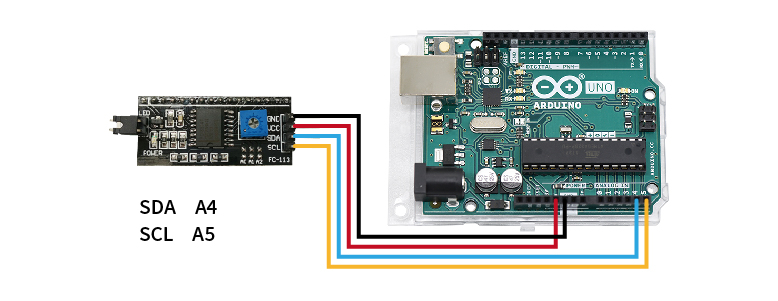
STEP 1. 將欲查詢的模組連接至Arduino UNO(附圖為腳位參考,實際請比對商品標示接線)
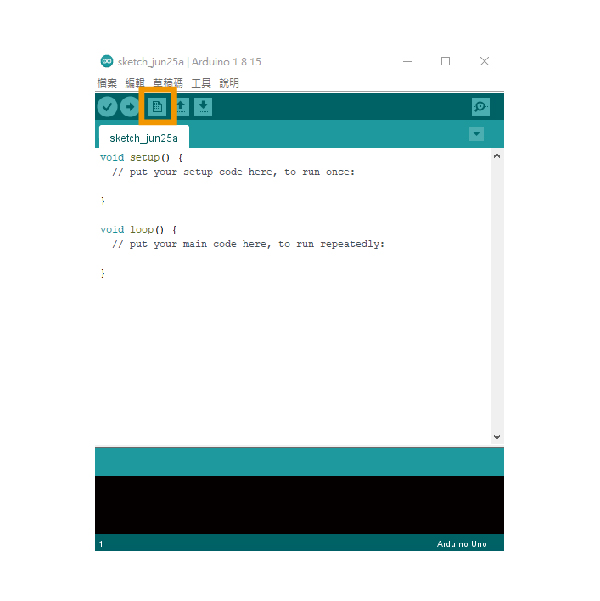
STEP 2. 開啟Arduino IDE並新增檔案
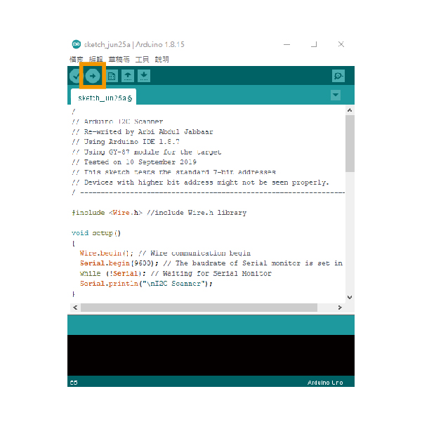
STEP 3. 貼入教學下方的範例文件,並上傳到Arduino UNO,即會開始掃描I2C位址
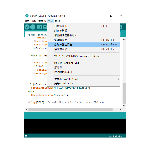
STEP 4. 開啟序列埠監控視窗,即可取得I2C位址
I2C掃描範例程式
| / ---------------------------------------------------------------- / |
| // Arduino I2C Scanner |
| // Re-writed by Arbi Abdul Jabbaar |
| // Using Arduino IDE 1.8.7 |
| // Using GY-87 module for the target |
| // Tested on 10 September 2019 |
| // This sketch tests the standard 7-bit addresses |
| // Devices with higher bit address might not be seen properly. |
| / ---------------------------------------------------------------- / |
| |
| #include //include Wire.h library |
| |
| void setup() |
| { |
| Wire.begin(); // Wire communication begin |
| Serial.begin(9600); // The baudrate of Serial monitor is set in 9600 |
| while (!Serial); // Waiting for Serial Monitor |
| Serial.println("\nI2C Scanner"); |
| } |
| |
| void loop() |
| { |
| byte error, address; //variable for error and I2C address |
| int nDevices; |
| |
| Serial.println("Scanning..."); |
| |
| nDevices = 0; |
| for (address = 1; address < 127; address++ ) |
| { |
| // The i2c_scanner uses the return value of |
| // the Write.endTransmisstion to see if |
| // a device did acknowledge to the address. |
| Wire.beginTransmission(address); |
| error = Wire.endTransmission(); |
| |
| if (error == 0) |
| { |
| Serial.print("I2C device found at address 0x"); |
| if (address < 16) |
| Serial.print("0"); |
| Serial.print(address, HEX); |
| Serial.println(" !"); |
| nDevices++; |
| } |
| else if (error == 4) |
| { |
| Serial.print("Unknown error at address 0x"); |
| if (address < 16) |
| Serial.print("0"); |
| Serial.println(address, HEX); |
| } |
| } |
| if (nDevices == 0) |
| Serial.println("No I2C devices found\n"); |
| else |
| Serial.println("done\n"); |
| |
| delay(5000); // wait 5 seconds for the next I2C scan |
| } |
出貨清單
- Pololu 3通道廣角TOF雷射測距模組 (I2C) x 1