{{ 'fb_in_app_browser_popup.desc' | translate }} {{ 'fb_in_app_browser_popup.copy_link' | translate }}
{{ 'in_app_browser_popup.desc' | translate }}
{{word('consent_desc')}} {{word('read_more')}}
{{setting.description}}
價格均為含稅價,滿1000元享免運優惠!歡迎公司及學校機關團體大量採購,由專人提供專案報價。
{{ childProduct.title_translations | translateModel }}
{{ getChildVariationShorthand(childProduct.child_variation) }}
{{ getSelectedItemDetail(selectedChildProduct, item).childProductName }} x {{ selectedChildProduct.quantity || 1 }}
{{ getSelectedItemDetail(selectedChildProduct, item).childVariationName }}
產品貨號:368031000498
區號:Lb01-04
品牌:Adafruit
原廠貨號:2264
全店,滿千免運優惠(限郵寄和超商純取貨)
商品存貨不足,未能加入購物車
您所填寫的商品數量超過庫存
{{'products.quick_cart.out_of_number_hint'| translate}}
{{'product.preorder_limit.hint'| translate}}
每筆訂單限購 {{ product.max_order_quantity }} 件
現庫存只剩下 {{ quantityOfStock }} 件
驅動微型 OLED 顯示器、讀取顏色感測器,甚至直接從計算機上閃爍一些 LED 不是很酷嗎? 當然,您可以對 Arduino 或 Trinket 進行編程以與這些設備和您的計算機對話,但是為什麼您的計算機不能僅與這些設備和感測器本身對話? 好吧,現在您的計算機可以使用 Adafruit FT232H 分線板與設備通信!
FT232H晶片能做什麼? 來自 FTDI 的這款晶片類似於他們的 USB 到串行轉換器晶片,但增加了一個“多協議同步串行引擎”,使其能夠使用許多常見協議,如 SPI、I2C、串行 UART、JTAG 等! 甚至還有一些數字 GPIO 引腳,您可以讀取和寫入它們來執行閃光燈 LED、讀取開關或按鈕等操作。 FT232H 的突破就像在您的計算機上為串行協議添加一把小瑞士軍刀!
當您想使用 Python(例如)快速迭代和測試使用 I2C、SPI 或普通通用 I/O 的設備時,該晶片功能強大且有用。 沒有固件需要處理,因此您不必處理如何“將數據發送到 Arduino 和從 Arduino 發送數據,然後再發送到”電子感測器或顯示器或部件。 這個突破有一個 FT232H 晶片和一個用於板載配置的 EEPROM。 您可以從 FTDI 的頁面上閱讀更多關於該晶片的訊息,並查看我們的程式,了解如何開始使用我們的 Python 代碼通過 Mac/Win/Linux 控制 FT232H。
有想像過在你的電腦或筆電上面銜接一些電子模組嗎?現在你可以透過 Adafruit FT232H Breakout 輕易的達到你要的效果。支援 GPIO + SPI + I2C 的 Arduino 或樹莓派模組。您可以在 Windows 或 Mac 上透過本模組銜接這些常見的設備。並且可以簡單的透過 python 或者 c 來控制這些設備
FT232H晶片能做什麼?來自FTDI的這款晶片 類似於其USB轉串行轉換器晶片,但增加了一個“多協議同步串行引擎”,可以使用諸如SPI,I2C,串行UART,JTAG等常見協議!甚至還有一些數字GPIO引腳,您可以讀寫來執行閃光燈,讀取開關或按鈕等。FT232H的突破就像為您的計算機添加一個用於串行協議的小瑞士軍刀!
操作流程
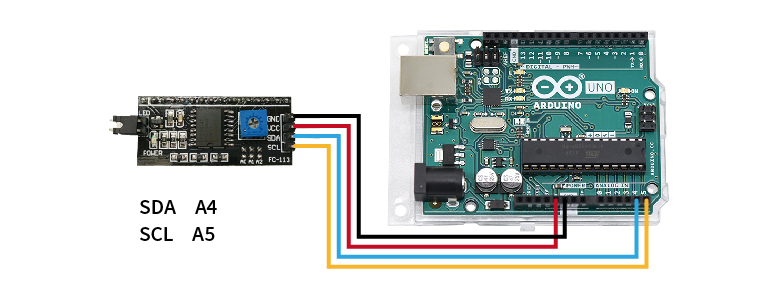
STEP 1. 將欲查詢的模組連接至Arduino UNO(附圖為腳位參考,實際請比對商品標示接線)
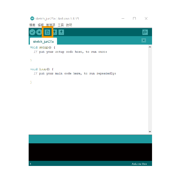
STEP 2. 開啟Arduino IDE並新增檔案
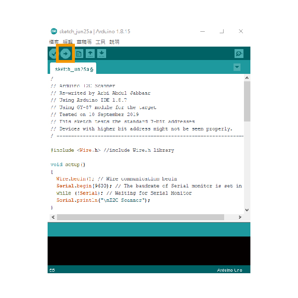
STEP 3. 貼入教學下方的範例文件,並上傳到Arduino UNO,即會開始掃描I2C位址
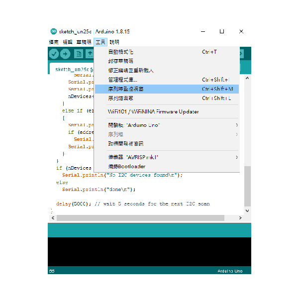
STEP 4. 開啟序列埠監控視窗,即可取得I2C位址
I2C掃描範例程式
/ ---------------------------------------------------------------- / | |
// Arduino I2C Scanner | |
// Re-writed by Arbi Abdul Jabbaar | |
// Using Arduino IDE 1.8.7 | |
// Using GY-87 module for the target | |
// Tested on 10 September 2019 | |
// This sketch tests the standard 7-bit addresses | |
// Devices with higher bit address might not be seen properly. | |
/ ---------------------------------------------------------------- / | |
#include //include Wire.h library | |
void setup() | |
{ | |
Wire.begin(); // Wire communication begin | |
Serial.begin(9600); // The baudrate of Serial monitor is set in 9600 | |
while (!Serial); // Waiting for Serial Monitor | |
Serial.println("\nI2C Scanner"); | |
} | |
void loop() | |
{ | |
byte error, address; //variable for error and I2C address | |
int nDevices; | |
Serial.println("Scanning..."); | |
nDevices = 0; | |
for (address = 1; address < 127; address++ ) | |
{ | |
// The i2c_scanner uses the return value of | |
// the Write.endTransmisstion to see if | |
// a device did acknowledge to the address. | |
Wire.beginTransmission(address); | |
error = Wire.endTransmission(); | |
if (error == 0) | |
{ | |
Serial.print("I2C device found at address 0x"); | |
if (address < 16) | |
Serial.print("0"); | |
Serial.print(address, HEX); | |
Serial.println(" !"); | |
nDevices++; | |
} | |
else if (error == 4) | |
{ | |
Serial.print("Unknown error at address 0x"); | |
if (address < 16) | |
Serial.print("0"); | |
Serial.println(address, HEX); | |
} | |
} | |
if (nDevices == 0) | |
Serial.println("No I2C devices found\n"); | |
else | |
Serial.println("done\n"); | |
delay(5000); // wait 5 seconds for the next I2C scan | |
} |